Question. What are Allen Keys?

Answer: Allen keys are used to tighten or loosen socket cap screws.
 |
| This was modeled by https://grabcad.com/sutikshan.bhardwaj-1 |
Answer: A cap screw is like your ordinary screw, but instead of the hex being in the outside, it is in the inside like a socket.
Question. OK... Can we see all the parts of the Allen Key set?

Question: Wow that's a lot of parts... what did you do first?
Answer: Well... Here are the steps I followed...
Step 1:
You have to go to insert > sheet metal

Question. How did get the measurements?
Step 2:

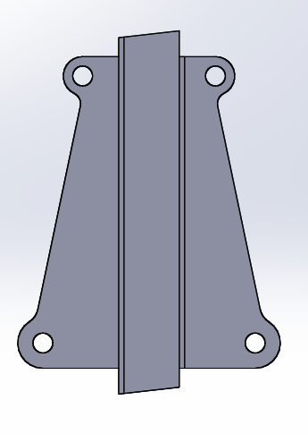
Answer. I started by tracing the body of the Allen Keys on a piece of paper to get the exact measurements to make this model as real life as possible.
Question: How did you transfer the measurements to the computer?
Step 3:

Answer: I first drew a dotted line, and then afterwards I sketched half of the body and then mirrored it.
Question: How do you add thickness to the sketch?
Step 4:
Go to insert> baseflage

Answer: By using "Baseflange", you can add thickness.
Question: How do you fold a "Baseflange"?
Question: How do you fold a "Baseflange"?
Step 5:

Answer: First you draw dotted lines where I drew the blue lines.
Question: Next... What feature do you use to make the fold?
Step 6:

Answer: You go to insert, sheet metal, and then bends and press the first dotted line. and then you do the same thing on the second dotted line.
Question: What do you do if you make a mistake in the pattern?
Question: What do you do if you make a mistake in the pattern?
Step 7:

You do the same thing as above but instead of pressing bends, you press on unfold.
Step 8:
Make lines like how I did below on both sides and then cut extrude.

Question: Why on earth does it mater if I cut the sides?
A. I will tell you why, because if you don't cut the sides and just skip ahead and bend them, when you go and try to bend everything, it would say it cannot happen because of an error.
Step 9:
It should end up looking like this:

Question: Why fold?
Step 10:
Fold

Answer: Simple, to cut the sides and know how much to cut
Step 11:
Draw lines across like that.
Question: Why draw these lines?

Answer: Why? I'll tell you why, it is because in order to do the next step (fold) we will need to draw the lines.
Step 12:
Go to insert, sheet metal, sketched bend.
Question: Whats the point of bending the small sides?

Answer. In order for the actual keys not to fall, you need this bend so they can be restricted and can only go so far.
Question. What did I do next when I finished the body?
Answer. I went on to do the bolts.
Question: How do we start?
Step 13:
Answer: You sketch a circle and the diameter must be.28 .

Step 14:
Go to features> Reference Geometry> and then Plane.

Step 15:
Question; Whats the point of making another plane if you can just use the same one?
A. The point of making another plane is that if you just use the same one the two sketches would just make a cylinder shape instead of making a cone type shape.

Step 16:
Draw a circle on the new plane and make the diameter .54

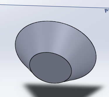
Step 17:
Then you go to features>lofted boss/base> and press the both circles and it would end up looking like how it looks below
Step 18:
Sketch on plane 1 on the smaller circle, click on the hexagon and sketch it in the middle at any size, then go to sketch>start dimension and make the hexagon the size of .16

Step 19:
Go to features>cut extrude> then make it .07in long and then the check

Step 20:
On the back of the bigger circle, sketch a circle in the middle and make it .22in

Step 21:
Go to features>boss extrude> blind> 1.30in long the click the check

Step 22:
Go to features>reference geometry>then axis and make the axis like how i have it (its the doted line)

Step 23:
Go to sketch>click on spline>and sketch that little curved line I have there.

Step 24:
Go to Features>revolved Boss/Base>press on the axis we made for where it says "axis of revolution"> Blind> and 360 degrees

Question. Now that I have finished the bots, what do I do next?
Answer. I had the circle
Step 25:
Sketch circle>then sketch a smaller circle inside of it>make the bigger circles diameter .56>then go on sketch>start dimension> then click on both circles and make the inside distance of both circles .15

Step 26:
Go to features>extruded boss/base> then make it blind> and make it 0.01in

Question: Now that I am almost done, do I have any ideas of what my next project would be?
Answer. As of right now, I do not know what my next project would be but I'm sure I will have at least one more after this one.
Okay, now that we have made both the bolt and the circle, we will now be making the actual key for the Allen key set.
Step 27:
For step 26, you would have to measure each real object and put in each and every allen key you make, you first make a straight light>then a little arc>than a sline to make the figure below

Step 28:
Make a hexagon at the end of the cane. And make it .14in

Step 29:
Go to Features>swept Boss/Base>and do what I did below.

Step 30:
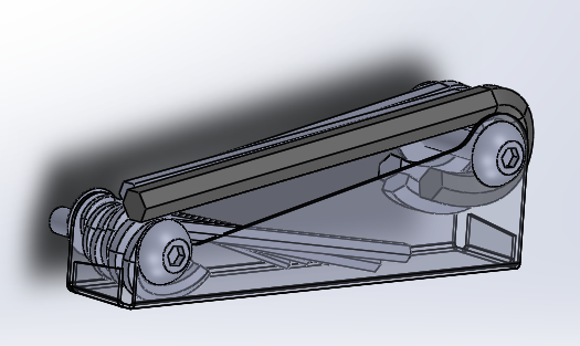
That is how everything is supposed to look. To make the other keys, just do steps 26-28 over but change the measurements.

Tada!
No comments:
Post a Comment